Navigation
RFP1 calibration
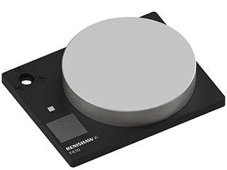
FA10 calibration artefact
Data collected by RFP1 is in the same reference frame as data collected by the REVO-2 tactile probes. The FA10 artefact is used to calibrate RFP1 and provides the link between RFP1 and the tactile reference frame.
The calibration routines are automatically controlled by UCCsuite and proceed as follows:
Locating the FA10 artefact using RSP2 and providing the tactile data for linking to RFP1
1. Fix the FA10 artefact onto the bed of the CMM as shown at the end of this section ('Fixing FA10 calibration artefact to CMM').
2. Run the routine in UCCsuite to locate the FA10 artefact using a calibrated RSP2 tool:
- The software will prompt the user to position the RSP2 above the location peg on the pillar of the FA10 artefact
- The remainder of the moves will be performed automatically
- Care must be taken to ensure that there is enough space / machine volume around the FA10 artefact to reach all parts of the artefact
3. Points will be taken as follows:
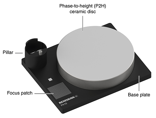
- On the location peg to determine height and initial location
- On the pillar to determine orientation of the artefact
- On the chequerboard target to determine position
- Around the circumference of the phase-to-height (P2H) disk to determine position
- On the P2H disc to determine plane height and axis
- On the focus patch to determine height
Calibrating an RFP1
1. At the start of the qualification process, the RFP1 will move from its current position to the safe position values defined in the FA10 dialogue box.
- User must take care to ensure that there is a clear line of sight from the current position to the FA10 safe position before requesting a qualification
2. Images will be taken on the P2H disk to normalise the illumination levels and set the triangulation spot position.
3. RFP1 will take images of the pillar to determine the properties of the camera lens.
- This aligns the RFP1 camera position to the REVO-2 reference frame, providing the link to RSP2 calibration
4. RFP1 will then take images of the P2H ceramic disc surface to calibrate the fringe pattern.
- The triangulation spot is also calibrated during this stage
5. A verification routine is performed automatically at the end of a qualification routine.
- RFP1 takes images of the pillar at different head angles to verify the lens parameters
Verification of an RFP1
1. At the start of the verification process, the RFP1 will move from its current position to the safe position values defined in the FA10 dialog box.
- User must take care to ensure that there is a clear line of sight from the current position to the FA10 safe position before requesting a verification
2. RFP1 takes images of the pillar at different head angles to verify the lens parameters.
Using FA10 for vision calibration
FA10 can also be used to calibrate RVP, instead of using the VA11 calibration artefact.
Fixing FA10 calibration artefact to CMM
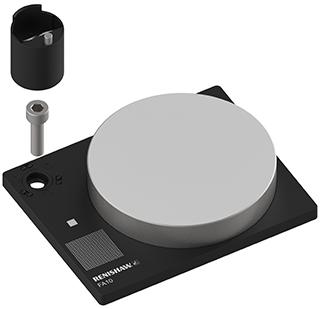
The FA10 calibration artefact is designed to be fixed securely to the bed of the CMM to allow accurate and repeatable calibration of RFP1. The diagrams below show how to fix the FA10 to the bed of the CMM.
- Locate an appropriate threaded hole in the bed of the machine.
- Position the artefact plate above the threaded hole.
- Screw the correct cap head bolt through the hole into the threaded hole on the machine. The supplied washer can be used to correctly fit smaller diameter bolts.
- Tighten with a hex wrench.
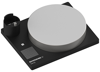
- Attach the calibration pillar to the kinematic mount. Integral magnets will secure it in place. Polarisation of the magnets will ensure the pillar is fitted in the correct orientation.